




















More and more geographic data is being collected in real time using sensors rather than manually. This enables organizations to respond more quickly to changes and ensures they always have access to up-to-date geographic information.
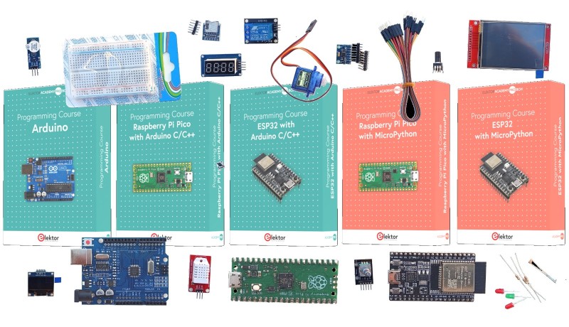
I used this IoT tutorial in a workshop I led at FOSS4G Europe 2026 in Romania. In another blog post, “Looking Back on FOSS4G Europe 2026 in Timișoara, Romania,” I share my experiences at that fantastic conference.
GIS has long since ceased to be solely about analyzing existing datasets. Geographic data is increasingly being collected in real time using IoT sensors. That’s why it’s becoming more and more important for geo-professionals to understand how sensor data is collected, processed, and fed into a GIS via Wi-Fi and protocols such as MQTT. This knowledge is indispensable in fields such as water management, infrastructure, agriculture, and smart cities. The blinking LED in this tutorial is the first step toward building professional Geo-IoT solutions with real-time geodata.
Every microcontroller project starts with an initial program. In this tutorial, you’ll learn how to set up the XIAO ESP32-C3, install the Arduino IDE, and upload a simple program that makes an LED blink.
Along the way, you’ll be introduced to the basics of the hardware, software, and programming workflow used for developing ESP32 projects.
Although a blinking LED may seem simple, it’s an important first step. Once you understand how to upload code and control hardware, you’ll be ready to build more advanced projects using sensors, wireless communication, and IoT technologies.
Before you upload your first program, you’ll need a few simple components. Don’t worry if you’ve never worked with electronics before: this circuit is easy to build and requires no soldering.
For this tutorial, you’ll need:
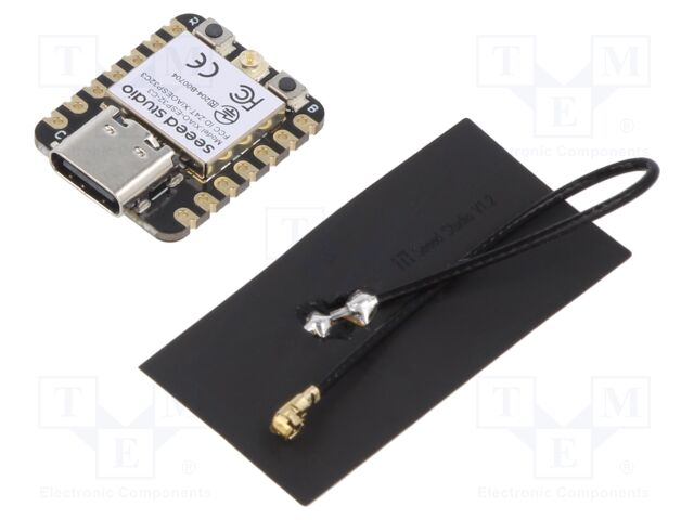
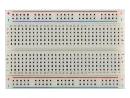
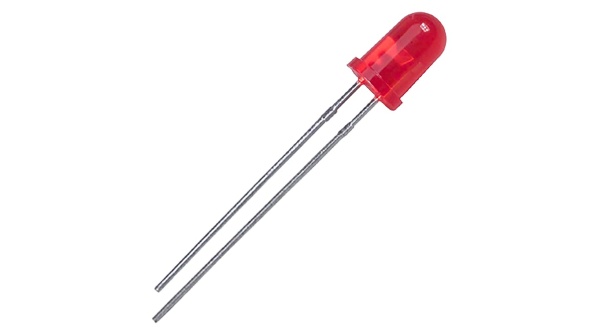
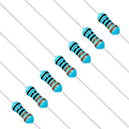
Now that you have all the necessary components, you can connect them to the breadboard as shown below:
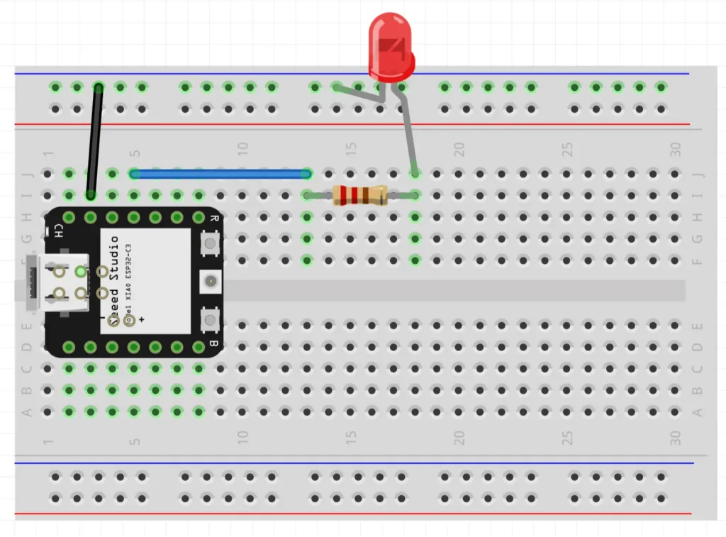
Now that the circuit is assembled, we need to tell the microcontroller what to do. To do this, we’ll program the XIAO ESP32-C3.
We’ll start by installing the Arduino IDE, configuring the software for ESP32 development, and connecting the board to the computer. Once everything is set up, we’ll upload our first program to make the LED blink.
On Windows:
.exe).On macOS:
.dmg).On Linux:
The Arduino IDE does not support the XIAO ESP32-C3 by default. You must therefore first add Espressif’s official package repository and then install the ESP32 board package.
Connect the XIAO ESP32-C3 to your computer using a USB-C cable.
Use a USB-C cable that supports data transfer. Some USB-C cables are only designed for charging devices. If the board doesn’t appear in the Arduino IDE, try using a different cable first.
Go to Tools > Board > esp32 and select XIAO_ESP32C3. You can also use the board selector at the top of the Arduino IDE window and search for XIAO_ESP32C3.
Go to Tools > Port and select the USB serial port associated with the board. You can also select it using the board selector at the top of the Arduino IDE window.
On Windows, this is usually a COM port, such as COM3, COM4, or a higher number. On macOS or Linux, the name usually starts with /dev/.
Not sure which port corresponds to the board? Disconnect the board, view the list of ports, reconnect the board, and check which port has appeared.
With any luck, everything went well and your program does absolutely nothing. Perfect. That means you can successfully program the board.
Copy and paste the code below, then upload it to your XIAO by clicking the right-pointing arrow in the Arduino IDE.
// XIAO has no built-in LED.
#define LED_NOTBUILTIN D10

void setup() {
  pinMode(LED_NOTBUILTIN, OUTPUT);
}

void loop() {
  digitalWrite(LED_NOTBUILTIN, HIGH);
  delay(1000);
  digitalWrite(LED_NOTBUILTIN, LOW);
  delay(1000);
}
That’s it! If everything went well, the LED should now be blinking.
If the upload gets stuck on "Connecting…," press the RESET button as soon as this message appears and try uploading again.
Congratulations!
You have successfully programmed your first XIAO ESP32-C3 and controlled an external LED.
Would you like to continue building practical IoT projects? Then the course “From Sensor to Board with C++ and XIAO ESP32 C3” takes you beyond the basics. You’ll learn how to connect sensors, send data via Wi-Fi, work with MQTT, generate GeoJSON, and visualize real-world sensor data on interactive maps.


More and more geographic data is being collected in real time using sensors rather than manually. This enables organizations to respond more quickly to changes and ensures they always have access to up-to-date geographic information.
IoT sensors collect data such as temperature, water levels, air quality, and GPS locations. GIS uses this data to analyze it spatially and visualize it on maps, revealing patterns and trends.
Geo-IoT is used in areas such as water management, infrastructure, agriculture, environmental monitoring, smart cities, and asset management. In all of these sectors, real-time sensor data helps monitor and manage objects and the environment.
More and more GIS projects are using live sensor data. By understanding how this data is collected, transmitted, and processed, GIS professionals can develop and manage comprehensive Geo-IoT solutions.
A basic understanding of programming is a major advantage. Using simple languages such as C++, you can control sensors, collect data, and automatically send it to GIS platforms, web maps, or databases. This gives you greater control over the entire data chain.