Every microcontroller project starts with a first program. In this tutorial, you’ll learn how to set up the XIAO ESP32-C3, install the Arduino IDE, and upload a simple program that makes an LED blink. Along the way, you’ll become familiar with the basic hardware, software, and programming workflow used for ESP32 development.
While blinking an LED may seem simple, it is an important first step. Once you understand how to upload code and control hardware, you’ll be ready to build more advanced projects using sensors, wireless communication, and IoT technologies.
Before uploading your first program, you’ll need a few basic components. Don’t worry if you’ve never worked with electronics before, this circuit is simple to assemble and requires no soldering.
For this tutorial, you’ll need:
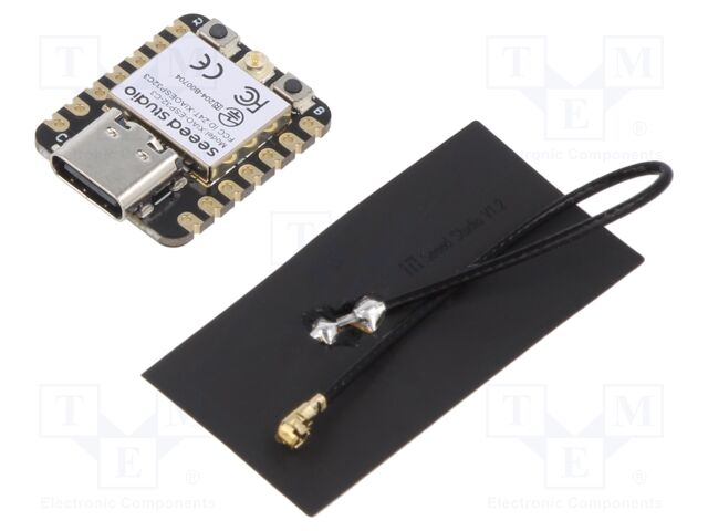
The Microcontroller is the brain of the sensor setup: XIAO-ESP32-C3
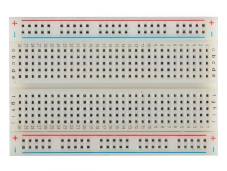
A breadboard for connecting everything without soldering (learn more at https://learn.sparkfun.com/tutorials/how-to-use-a-breadboard/all)
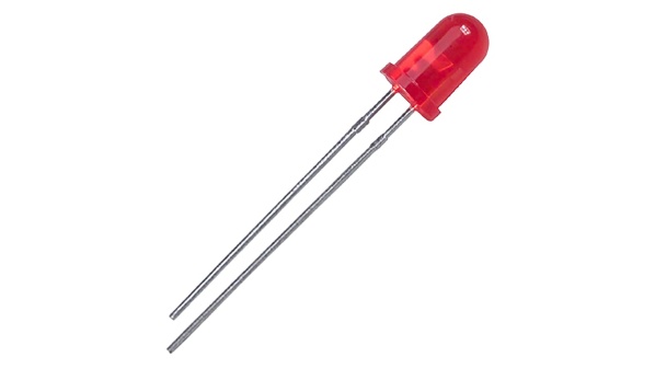
An LED (long leg is +)
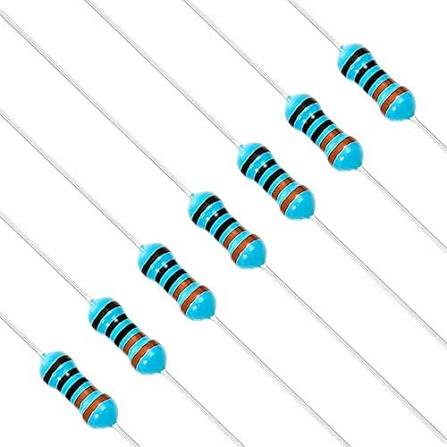
A 330-ohm resistor to prevent the LED from burning out
Now that you have all the required components, connect them on the breadboard as shown below:
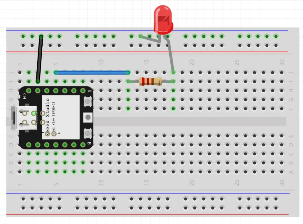
Breadboard visualization of hardware setup
Now that the circuit is assembled, we need to tell the microcontroller what to do, for this we can program the XIAO ESP32-C3.
We’ll first install the Arduino IDE, configure it for ESP32 development, and connect the board to the computer. Once everything is set up, we’ll upload our first program to make the LED blink.
On Windows:
.exe file.On MacOS:
.dmg file.On Linux:
Arduino IDE does not support the XIAO ESP32C3 by default. You first need to add the official Espressif package source and install the ESP32 board package.
Connect the XIAO ESP32C3 to your computer with a USB-C cable.
Use a cable that supports data. Some USB-C cables can only charge devices. If the board does not appear in the Arduino IDE, try another cable first.
Open Tools > Board > esp32 and select XIAO_ESP32C3. You can also use the board selector at the top of the Arduino IDE window and search for XIAO_ESP32C3.
Open Tools > Port and select the USB serial port that belongs to the board. You can also select it through the board selector at the top of the Arduino IDE window.
On Windows this is usually a COM port, for example COM3, COM4, or a higher number. On macOS or Linux the name usually starts with /dev/.
If you are not sure which port is the board, unplug the board, look at the port list, plug the board in again, and check which port appeared.
With a bit of luck, everything worked and your program does absolutely nothing. Great. That means the board can be programmed.
Copy and paste this code, then upload it to your XIAO using the arrow pointing to the right in Arduino IDE.
// XIAO has no built-in LED.
#define LED_NOTBUILTIN D10

void setup() {
  pinMode(LED_NOTBUILTIN, OUTPUT);
}

void loop() {
  digitalWrite(LED_NOTBUILTIN, HIGH);
  delay(1000);
  digitalWrite(LED_NOTBUILTIN, LOW);
  delay(1000);
}
That’s it: your LED should now be blinking!
If uploading gets stuck on Connecting…, press RESET when the message appears and try the upload again.
Congratulations! You’ve successfully programmed your first XIAO ESP32-C3 and controlled an external LED.
If you’d like to continue building practical IoT projects, the From Sensor to Map with C++ and XIAO ESP32-C3 course takes you beyond the basics. You’ll learn how to connect sensors, transmit data over Wi-Fi, work with MQTT, create GeoJSON, and visualize real-world sensor data on interactive maps.